The challenges in a world of ever increasing complexity of (integrated) electronic circuits are often addressed by greater automation, advanced design processes and more sophisticated tools. Even though these help to cope with more complex designs, they also introduce more complexity in the design flow itself. Running the sequence of design automation tools that are necessary to accomplish the design is in itself a challenge that the designer must handle.
Often, your design flow uses a sequence of EDA tools from different vendors to take the design from its concept to production files - an FPGA bitfile, a GDS2 layout… Furthermore, it often requires scripting skills to make all those tools work together, to prepare the output of one tool for the next step of the flow and start up the next tool with all required inputs and parameters. A scripted design flow takes effort to set up and maintain, but offers flexibility, by letting the designers choose the most suitable tool for each step of the flow.
Integration of tools in the design flow reduces the amount of
scripting needed to run the flow. Not only does it speed up the
designers’ work. Integration also reduces the risk of mistakes.
In this article, we’ll discuss how Sigasi Visual HDL (SVH) fits into your
design flow - and maybe how your design flow fits into SVH.
Other examples of integrated environments are FPGA design
suites like Intel Quartus and Xilinx Vivado. Obviously, their use is
limited to designs for FPGAs from one particular supplier.
Design flow
The picture below illustrates an overview of the design flow of a digital circuit. The flow starts from the design specification. Often, all or part of the design specification is translated directly by R&D engineers into a Register Transfer Level (RTL) design. Sometimes, parts of the RTL design are generated, e.g. using High-Level Synthesis . IP cores , which implement functionality required in the design, are integrated at this stage, too. Functional RTL simulation and formal verification are used to verify that the RTL design meets the specification.
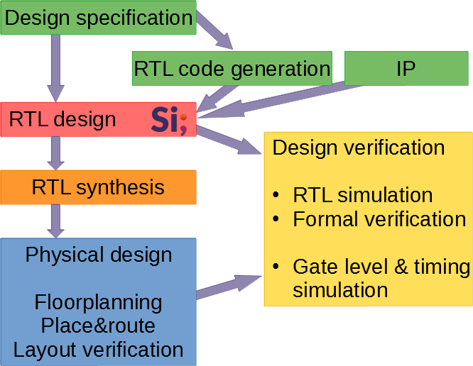
Once the RTL design is finished, an RTL synthesis tool translates the RTL code into a netlist of basic components of the design’s target technology (FPGA, ASIC…). Then follows the physical design with a.o. floorplanning, placement, routing and layout verification. Verification (simulation) follows RTL synthesis, placement and routing to verify that the design still meets its specification.
An important difference exists between the earlier steps of the design flow (specification and RTL design) on the one hand, and the later steps (RTL synthesis and physical design) on the other hand. RTL synthesis and physical design are largely automated. In contrast, RTL design in particular is highly manual, in a sense that much of the RTL design is hand-coded by the design engineers.
RTL design is where SVH and the Sigasi extension for Visual Studio Code help to ease the designers' life. The Sigasi tools support the designer with design entry, debugging and maintenance. SVH also reads in IP libraries and generated designs, and assists the designer with integrating these into a larger system.
Sigasi tools integrate seamlessly into the design flow, which leads to fewer and simpler scripts being required to run the flow. In the next paragraphs, we’ll show how Sigasi tools help with running the design flow.
Simulator integration
SVH is integrated with a number of popular simulators. The simulator integration consists of two elements.
First of all, Sigasi tools can compile your design with your simulator’s compiler every time when you save a file. Errors and warnings from your simulator’s compiler are presented in Sigasi’s editor and problems view. Designers get immediate feedback on whether their code is compatible with their simulator, which helps them to write correct code more quickly. Also, the designer doesn’t need to maintain a script to compile all design files in the correct order, SVH does this for you.
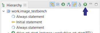
SVH also has a button to start the simulator. No need to type a simulator command in a terminal window or browse through a directory structure to find your working directory, one click in your IDE suffices.
Exporting and using the compile order
SVH features integrations with a number of popular simulators, but obviously, it wouldn’t be feasible to offer integrations with all imaginable design tools. As can be seen in the design flow, RTL design is followed by RTL design verification and RTL synthesis. Design tools for these steps in the design flow need, in addition to the design files, the compile order. The compile order is the order in which the design files should be read and compiled such that each file is compiled after the files on which it depends. For example, if a design unit instantiates a subdesign, the file containing the subdesign must be compiled first.
SVH can generate the compile order of a project as a CSV file. CSV (Comma-Separated Values) is a file format which can easily be parsed and used by scripts to drive other tools, e.g. RTL synthesis.
Using the exported compile order requires some scripting skills. With the exported compile order, the designer doesn’t need to maintain the compile order by hand. Scripts can be made generic so they can be reused for other projects without (or with minimal) changes.
An example: using the compile order directly in other tools
Many EDA tools have a built-in tcl interpreter as their scripting engine and command line interface. Here is an example of a generic script which may run inside e.g. an RTL synthesis tool to read in a design. The script uses the generated CSV file with the compile order. The script doesn’t contain any project-specific code so it can be reused for any project.
# Read the compile order as exported from SVH and
# compile each file
foreach row [split [read [open "compilation_order.csv" r] ] "\r\n"] {
  if {[string first "," $row] != -1} {
    # Split each non-empty row into its columns
    lassign [split $row ","] libname filename
    puts "Compiling [string trim $filename] into library $libname"
    # Extract the file extension to determine the design language
    set fileext [lindex [split $filename "."] end]
    switch -nocase $fileext {
      # Depending on file extension, call the appropriate compile command
      #
      # You may need to change read_verilog and read_vhdl with your
      #   tool's functions to read and compile design files.
      "v"    { read_verilog     -lib $libname $filename }
      "sv"   { read_verilog -sv -lib $libname $filename }
      "vhd"  -
      "vhdl" { read_vhdl -lib $libname $filename }
    }
  }
}
So far, we have shown how SVH fits nicely into your design flow. But there is more.
Running the design flow from SVH
Yes, that’s right. You can also integrate your design flow in SVH. SVH already integrates a number of simulators, but you can add more steps of the design flow. What do you think of the following use cases?
- You have a tool which generates (the address map of) a configuration register file from a list of registers. Every time when you update the list, you want to re-run the tool to update the RTL design.
- You are making a fairly small (e.g. FPGA) design and you want to run the FPGA implementation flow regularly. Switching to the FPGA tool each time is inconvenient, running the implementation flow from within the RTL design environment is quicker and easier.
- You are working on a large design. From time to time, you want to run the compilation stage of RTL synthesis on your subdesign as a sanity check. The RTL tool expert in the team prepares a setup so you can run the sanity check from within the RTL design environment.
Let’s have a look at a couple of examples.
Generating HDL code
As the size and complexity of designs is increasing, it is a good idea to move the design entry to higher levels of abstraction where possible. From the higher level design, one can generate the RTL code, which is more efficient and less error-prone than hand-coding. Examples of tools that translate higher-level designs into RTL include:
- High-Level Synthesis, which translates algorithms from a classical programming language (e.g. C) into an RTL design;
- Tools which generate the top level of an RTL design, taking care of the integration of various IP and custom logic blocks;
- Tools and scripts which generate smaller parts of a design, e.g. a configuration register file.
As an example, we’ll look at a simple script which generates the address map of a register file from a list of registers. An earlier article shows how to set up a simple code generator. Every time when the list of registers is updated, the VHDL package file is re-generated according to the new specification.
| Registers table | Generated VHDL package |
|---|---|
registers = [("foo",0x0004cafe),("bar",0x00facade),("baz",0xbeefcafe),("tor",0x23413411),("top",0x13413415)] | package p isconstant foo_address : integer := 16#0004cafe#;constant bar_address : integer := 16#00facade#;constant baz_address : integer := 16#beefcafe#;constant tor_address : integer := 16#23413411#;constant top_address : integer := 16#13413415#;end package p; |
Obviously, the example can be improved in various ways. The register list can be read from a separate (spreadsheet-like) file, rather than being part of the script. The script could generate the RTL code of the entire register file rather than just the address map. But, while this is a very basic example, it shows the strengths of the approach:
- Maintaining a list of registers is easier than hand-writing RTL code for the whole register file and updating the RTL code by hand when the list changes.
- The automatic build ensures that the RTL code is always up to date with the design definition (register list).
Running the downstream design flow
A different use case of integrating external tools into SVH is running subsequent steps of the downstream design flow - RTL synthesis and beyond. Typically, these steps of the design flow take a bit longer, so you probably don’t want to run them whenever a file is saved. But being able to run the flow from within SVH saves you from starting another GUI or running a series of commands from a command shell.
The simplified example which we’re going to discuss runs an entire FPGA implementation flow using Xilinx Vivado. With some tweaks here and there, the example can be adapted for other FPGA vendors and ASIC tools, or shortened to only run the initial steps of the flow as a sanity check. In the following sections, we’ll see how to configure and run the FPGA flow.
1. Export the compile order
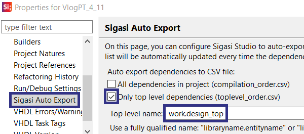
First, we configure SVH to export the list of design files in the order in which they need to be compiled. In order to have SVH export the compile order every time a file is saved, go to Project > Properties > Sigasi Auto Export, check Only top level dependencies and enter the top level of the design as shown.
2. Scripts setup
Now it’s time to set up the scripts to run the FPGA flow. In this example we’re using two scripts: a shell script to start the FPGA tool, and a tcl script which runs the flow inside the FPGA tool. You’re welcome to modify these scripts according to your needs. Before running these scripts from within SVH, you can test them from the command line (shell script) or the Vivado CLI/GUI (tcl script). Once the scripts are working, you’re ready for the next step.
3. External tool configuration in SVH
Now we’ll set up the FPGA implementation flow as an external tool in SVH.
| Select Run > External Tools > External Tools Configurations..., then select Program and click the New launch configuration icon. | 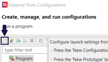 |
| In the dialog, set the Name of the launcher. In the Main tab, set the Location of the launch script (run_flow.sh) and the Working Directory. It is recommended to run the FPGA flow in a subfolder of the project folder. If a subfolder is used, the scripts need to reflect this. | 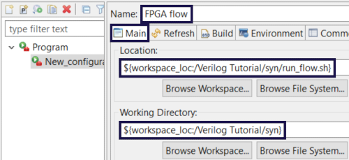 |
| Finally, in the Common tab, check the External Tools checkbox as shown. Then, click Apply and Close. | 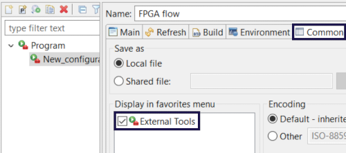 |
| Now select Run > External Tools > FPGA flow to run the FPGA flow from within SVH. | 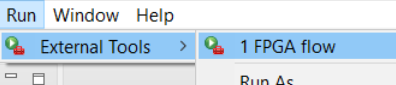 |
| In the Console view, you can follow the progress of the flow. | 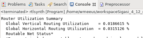 |
Wrapping it all up
In this article, we have shown that SVH fits nicely into the digital design flow. Simulator integration and the auto-generated export of the compile order are key features to this effect.
But also, we’ve shown that the design flow can be integrated into SVH. This way, SVH can be your design dashboard in which you create the design and operate the entire design flow.
See also
- Sigasi Studio Editing Tricks (legacy)
- Rapid Waveforms with GTKWave (blog post)
- The benefits of early detection (screencast)
- Sigasi's Software Development Kit Part 2 (legacy)
- Sigasi's Software Development Kit Part 1 (legacy)