My name is Felix, and I’ve been working at Sigasi for about a year and a half at the time of writing. My background is in software development and mathematics, so I took a VHDL course a year ago, together with some other colleagues, to get a better feel for the context I’m now working in.
Over the course of three days, we learned how to debug and check solutions by looking at waveforms. Being used to step-through debugging with some print statements thrown in for good measure, this was already quite different. The biggest shock for me, though, was the length of the debugging cycle in comparison with the software world. Going from having made a change in my code to launching a simulator and getting it to show me a waveform sometimes took several minutes! After a few exercises, I resorted to writing my initial solution in Sigasi Visual HDL (the autocomplete templates are just too helpful), while making small adjustments to debug my design in the rather primitive editor in the simulator.
On the morning of the second day, I resolved to improve things. I’d seen the instructor demonstrating simulations using the command line interface of some simulators, and those didn’t seem to have the launching time issues the graphical interfaces did. I still needed a graphical component to see the waveform, but some quick internet searches introduced me to GTKWave , and the basics for my future design cycle were set.
The configuration and scripts I wrote started collecting dust soon after the course was over. At Sigasi, we try to keep improving ourselves, though, and last month, some of us started doing some Verilog exercises together. I’ve brushed the dust off the work I did last year, and this time, I’m documenting it in a blog post so it doesn’t get lost again.
Throughout this post, I’ll be using the following VHDL design and its Verilog counterpart:
library ieee;
use ieee.std_logic_1164.all;

entity adder is
	port(
		a, b, cin : in  std_logic;
		s, cout   : out std_logic
	);
end entity adder;

architecture RTL of adder is
begin
	s    <= a xor b xor cin;
	cout <= (a and b) or (a and cin) or (b and cin);
end architecture RTL;
module adder ( input a, b, cin, output s, cout ); assign s = a ^ b ^ cin; assign cout = (a & b) | (a & cin) | (b & cin); endmodulelibrary ieee; use ieee.std_logic_1164.all; entity bench is end entity bench; architecture RTL of bench is signal a, b, cin, s, cout : std_logic; signal s2, cout2 : std_logic; signal correct : boolean; begin dut : entity work.adder port map(a => a, b => b, cin => cin, s => s, cout => cout); stim : process is type quint is array (natural range 0 to 4) of std_logic; begin (a, b, cin, s2, cout2) <= quint'('0', '0', '0', '0', '0'); wait for 10 ns; (a, b, cin, s2, cout2) <= quint'('1', '0', '0', '1', '0'); wait for 10 ns; (a, b, cin, s2, cout2) <= quint'('0', '1', '0', '1', '0'); wait for 10 ns; (a, b, cin, s2, cout2) <= quint'('1', '1', '0', '0', '1'); wait for 10 ns; (a, b, cin, s2, cout2) <= quint'('0', '0', '1', '1', '0'); wait for 10 ns; (a, b, cin, s2, cout2) <= quint'('1', '0', '1', '0', '1'); wait for 10 ns; (a, b, cin, s2, cout2) <= quint'('0', '1', '1', '0', '1'); wait for 10 ns; (a, b, cin, s2, cout2) <= quint'('1', '1', '1', '1', '1'); wait for 10 ns; wait; end process stim; correct <= (s = s2) and (cout = cout2); end architecture RTL;module bench; reg a, b, cin; wire s, cout; reg s2, cout2; wire correct; adder adder_instance(a, b, cin, s, cout); initial begin {a, b, cin, s2, cout2} <= 5'b00000; #10ns; {a, b, cin, s2, cout2} <= 5'b10010; #10ns; {a, b, cin, s2, cout2} <= 5'b01010; #10ns; {a, b, cin, s2, cout2} <= 5'b11001; #10ns; {a, b, cin, s2, cout2} <= 5'b00110; #10ns; {a, b, cin, s2, cout2} <= 5'b10101; #10ns; {a, b, cin, s2, cout2} <= 5'b01101; #10ns; {a, b, cin, s2, cout2} <= 5'b11111; #10ns; end assign correct = (s == s2) && (cout == cout2); endmodule
I’ve put these new super complex high-end designs in an example project, which you can download here. Like I said… I’m new to hardware design.
Setting up simulation tool
To generate the VCD files to feed into GTKWave,
I’ll use some of the integrated tools.
Sigasi has simulation tools for GHDL, ModelSim/Questa, and Riviera-PRO.
There’s also simulation integration using Xilinx Vivado,
but because Vivado’s xsim doesn’t support exporting waveforms,
I cannot use it here.
The other EDA tools configurable from Sigasi do not have simulation enabled.
GHDL is the easiest external compiler to set up, but unfortunately, it only works for VHDL. The other compilers require more tweaking, but they allow both VHDL and Verilog simulation. You can configure multiple compilers and select the active one in Window > Preferences > Sigasi > External Compilers.
GHDL
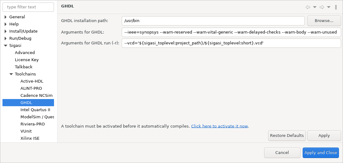
The default configuration in Window > Preferences > Sigasi > External Compilers > GHDL, as shown below, should already have the correct arguments. If not, you can click the Restore Defaults button to get them. You still need to set the GHDL installation path and activate the GHDL compiler in Window > Preferences > Sigasi > External Compilers.
When running the simulation with work.bench(RTL) as top level,
as detailed in the next section,
GHDL should write a file called bench.RTL.vcd to the root of the example project.
Note: It should write to the file ${sigasi_toplevel:project_path}/${sigasi_toplevel:short}.vcd,
where the first variable is replaced by the project root of the top level we’re simulating,
and the second variable is replaced by the name of the top level without the library.
ModelSim/Questa
The configuration for the ModelSim/Questa tool is found in Window > Preferences > Sigasi > External Compilers > ModelSim / Questa.

Again, you need to set the installation path.
Furthermore, you need to tell VSIM which simulation to run.
The arguments -c -do 'add wave -r /*; run -all; exit' tell VSIM to
- run the command line interface (
-c), - add all signals to the waveform (
add wave -r /*), - run the simulation, and
- exit.
Note that I had to uncheck Run simulation in its own window.
If I didn’t, Sigasi would have added the -gui option to the simulation arguments,
which conflicts with the -c option I want.
When hitting the simulate button in the hierarchy view,
as detailed in the next section,
VSIM will put a file called vsim.wlf in our project root.
GTKWave does not support WLF files,
so I had to use a tool unsurprisingly called wlf2vcd,
included in ModelSim, to convert this WLF file to a VCD file.
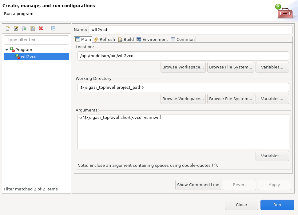
Go to Run > External Tools > External Tools Configurations… and double-click Program to create a new configuration.
Call the new configuration wlf2vcd, set the location of the executable,
use ${sigasi_toplevel:project_path} (the root of the simulated project) as the working directory,
and use -o '${sigasi_toplevel:short}.vcd' vsim.wlf as arguments.
You don’t have to change any of the other tabs, just Apply and Run.
A file called bench.RTL.vcd (or bench.vcd for Verilog) should appear in your project.
(Or the one from GHDL, if you configured that previously, would be overwritten.)
Note: If you are running this for the VHDL testbench,
you’ll get a warning that boolean is not supported by wlf2vcd,
and it won’t appear in the waveform.
You can replace it with a logic signal.
wlf2vcd Builder
While you could run this converter manually after simulation, this would increase the number of clicks to get a waveform from 2 (simulate button, refresh button in GTKWave) to a whole 4! You could bring that back down to 3 by adding the converter to the toolbar (Window > Perspective > Customize Perspective…, check Launch) but you can also keep it at 2 by adding an automatic builder. You can skip to the Riviera-PRO configuration or the simulation if you don’t mind manual conversion.
Right-click on the project to go to the project properties,
and open the Builders page.
Click Import… to copy the wlf2vcd external tool into the builders.
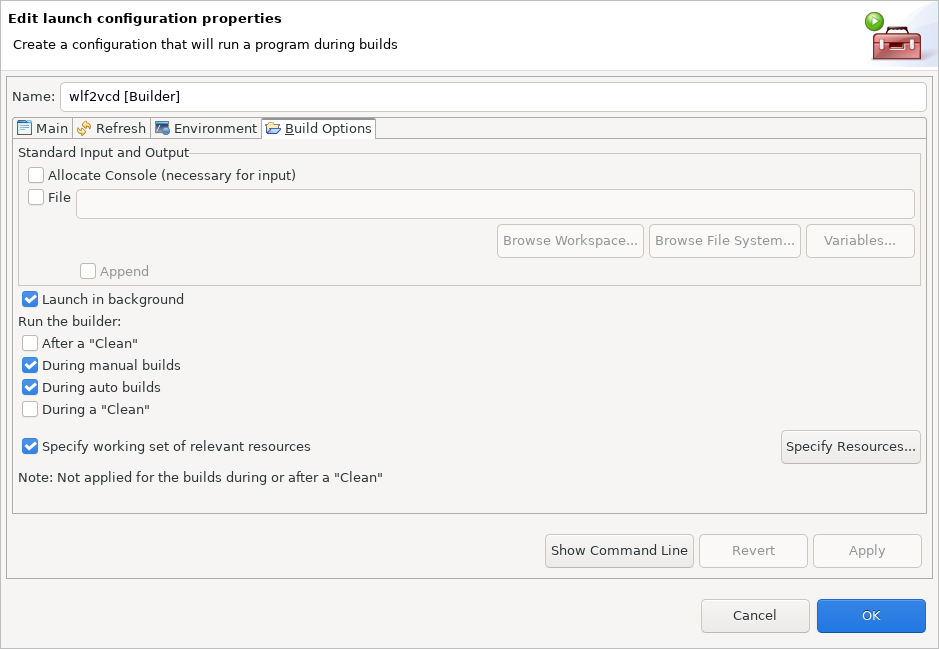
Edit the new builder and go to the Build Options tab.
You don’t have to “allocate a console” or “run after a clean,”
but you do want to “launch in background” and run “during auto builds.”
As “working set of relevant resources,” specify vsim.wlf in the current project.
Every change in vsim.wlf, including simulation runs,
should now trigger an execution of the external tool,
so the bench.RTL.vcd or bench.vcd waveforms should remain up-to-date.
Riviera-PRO
You can find the configuration for the Riviera-PRO tool in Window > Preferences > Sigasi > External Compilers > Riviera-PRO.
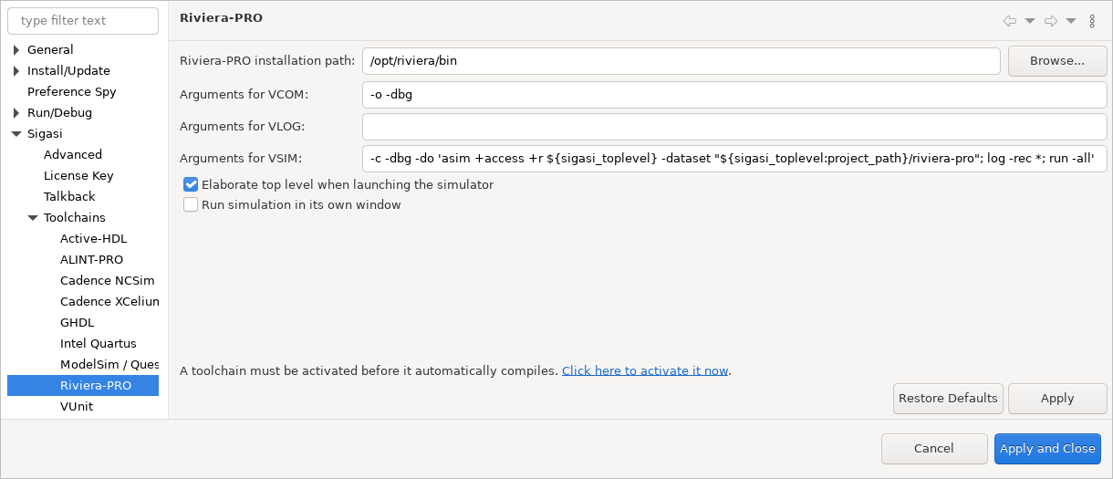
The configuration here is a tad more complex than the ModelSim/Questa one.
After setting the installation path,
I set the arguments for VSIM to -c -dbg -do 'asim +access +r ${sigasi_toplevel} -dataset "${sigasi_toplevel:project_path}/riviera-pro"; log -rec *; run -all'.
-crequests the command line interface. (Once more: uncheck Run simulation in its own window.)-dbgadds debugging symbols.asim +access +r ${sigasi_toplevel}gives the simulation read access to all signals in our top level unit, and-dataset "${sigasi_toplevel:project_path}/riviera-pro"tells Riviera-PRO to store its database in a directory called “riviera-pro” in our project.- With
log -rec *I ask to trace all signals, and finally run -allruns the simulation.
Note: For VHDL, I had to replace asim +access +r ${sigasi_toplevel} with asim +access +r work.bench. Riviera-PRO expects the name of the entity of the simulated architecture, for which Sigasi has no variable.
When running the Riviera-PRO simulation with the simulate button,
as detailed in the next section,
the file riviera-pro/dataset.asdb appears in your project root.
GTKWave does not support ASDB files,
but Aldec ships a tool called asdb2vcd with Riviera
that we can execute from Sigasi Visual HDL for Eclipse.
Go to Run > External Tools > External Tools Configurations… and double-click Program to create a new configuration.
Call the new configuration asdb2vcd,
set the location of the executable,
use ${sigasi_toplevel:project_path} as the working directory,
and use riviera-pro/dataset.asdb riviera-pro/waveform.vcd as arguments.
You don’t have to change any of the other tabs,
just Apply and Run.
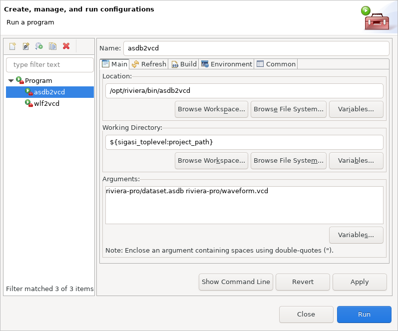
A file called riviera-pro/waveform.vcd should appear in your project.
asdb2vcd Builder
You can add a builder for this external tool just like I did for wlf2vcd in the ModelSim/Questa section,
simply replacing the imported external tool with asdb2vcd
and using riviera-pro/dataset.asdb as “working set of relevant resources.”
Simulation
Regardless of which toolchain you set up, you can set the top level you want to simulate and run the simulation using the two marked icons:

Visualization
After simulation, we want to visualize the waveform using GTKWave . GTKWave is an easy-to-use but fully featured wave viewer. Though it’s completely unrelated to Sigasi, we can configure it as an external tool from Sigasi Visual HDL for Eclipse.
Opening one of our generated VCD files, we’ll usually add all signals/wires to the waveform and zoom to fit. When you run another simulation and the waveform changes, you can just click the refresh button.
Conclusion
This tool should be helpful for small units in large designs. It may need more configuration to be useful on larger modules, but I’m quite happy with the current behavior while learning Verilog. I’m hoping someone else finds it here and thinks it’s useful, too. Did you? Let me know in the comments!
See also
- The benefits of early detection (screencast)
- Sigasi Studio Editing Tricks (legacy)
- Sigasi Visual HDL in your design flow, and vice versa (blog post)
- Cross project includes in SystemVerilog (legacy)
- Eclipse Tcl support in Sigasi (legacy)