This page documents the views the SVH extension adds to VS Code.
Sigasi Projects View
The Sigasi Projects View offers a file browser for your projects, including external folders that are not physically part of your project. This can be useful for including external IP in your projects.

The Projects View also offers a lot of custom Sigasi functionality, such as library mapping, version setting, and displaying the Preference View.
Linked Libraries
You can add any (external) libraries and files not within an open project’s folder using the Sigasi Projects View.
In the Sigasi Projects View, right-click any file or folder and select the New Linked File… or New Linked Folder… option to add files and folders from outside the project location.
The configuration of these external files and folders will be kept in the .project file in the project root.
You can add external files and folders anywhere in a project.
If you add a large folder, for example, the unisim primitives, make sure to exclude the folder (Right-click > Set Library > Exclude from Build) from being built and only include the required files.
Alternatively, you can put the library files in a folder called Common Libraries.
Then they will only be indexed and not analyzed for errors.
Buttons in the Sigasi Projects View
These buttons are available in the Sigasi Projects View:
 Create a new file
 Create a new folder
 Refresh
 Collapse all folders in the Sigasi Projects View
 More Actions
- Toggle Follow Cursor (links the Sigasi Projects View with the editor)
Hierarchy View
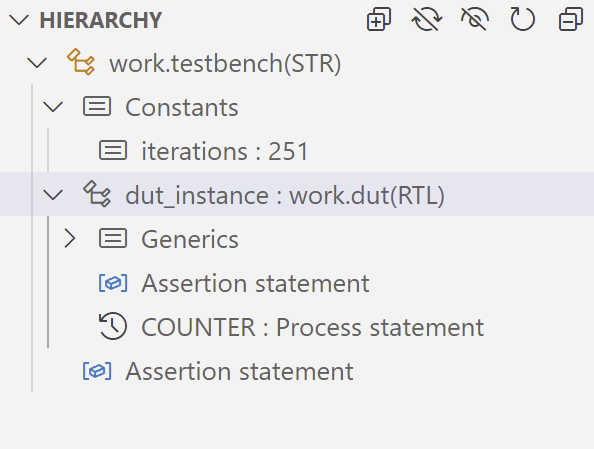
Initially, the Hierarchy View will be empty. To use the Hierarchy View, right-click an entity, architecture, or module name in the editor and select Set as Top Level from the pop-up menu. This will populate the Hierarchy View with the structure of your top level.
As you make changes to the design, the Hierarchy View will not automatically refresh.
To refresh the Hierarchy View, use the refresh button ().
If you want the selection in the Hierarchy View to follow your position in the editor, make sure to enable Follow Cursor from the More Actions () menu.
Buttons in the Hierarchy View
These buttons are available in the Hierarchy View:
 Expand the full hierarchy
 Only show Instantiations (enabled)
 Only show Instantiations (disabled)
- Refresh the Hierarchy View
- Collapse the hierarchy
- More Actions
- Toggle Follow Cursor (links the Hierarchy View with the editor)
- Toggle Auto Refresh on save
- Sort by: Position
- Sort by: Name
- Sort by: Category
Problems View
The Problems View shows problems (errors, warnings, or info) related to your code. The Problems View is located at the bottom window by default. If it is not open, you can open it by going to View > Open View… and then selecting Problems.
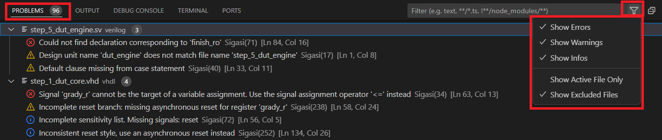
Using the Problems View, you can navigate to the source of a problem by double-clicking on it. You can filter problems by using the filter icon located at the top-right.
Libraries View

The Libraries View shows the library mapping as well as the description style of the design units in all projects. You can use it to navigate to a particular design unit in your project. When you click on a file, it will open in the editor.
UVM Topology View
Sigasi Visual HDL Professional Edition or Sigasi Visual HDL Enterprise Edition, [Only for SystemVerilog]
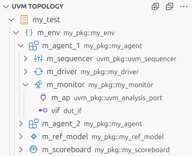
The UVM Topology View shows the verification environment’s component topology. To view a component’s topology, right-click its class name in the editor and select Set as Root UVM Component from the pop-up menu. This will populate the UVM Topology View with the structure of the selected component and its children, including their ports and virtual interfaces.
As you make changes to the design, the UVM Topology View will automatically refresh.
You can navigate to a topology element in an editor by double-clicking it. Right-clicking an element opens a context menu with more navigation options: you can open the type, declaration, or instantiation of a selected element in an editor.
Buttons in the UVM Topology View
These buttons are available in the UVM Topology View:
- Expand all components
- Collapse all components
Other available actions:
- Sort components, ports, and interfaces alphabetically.
- Sort components, ports, and interfaces by position in the source code.
Preference View
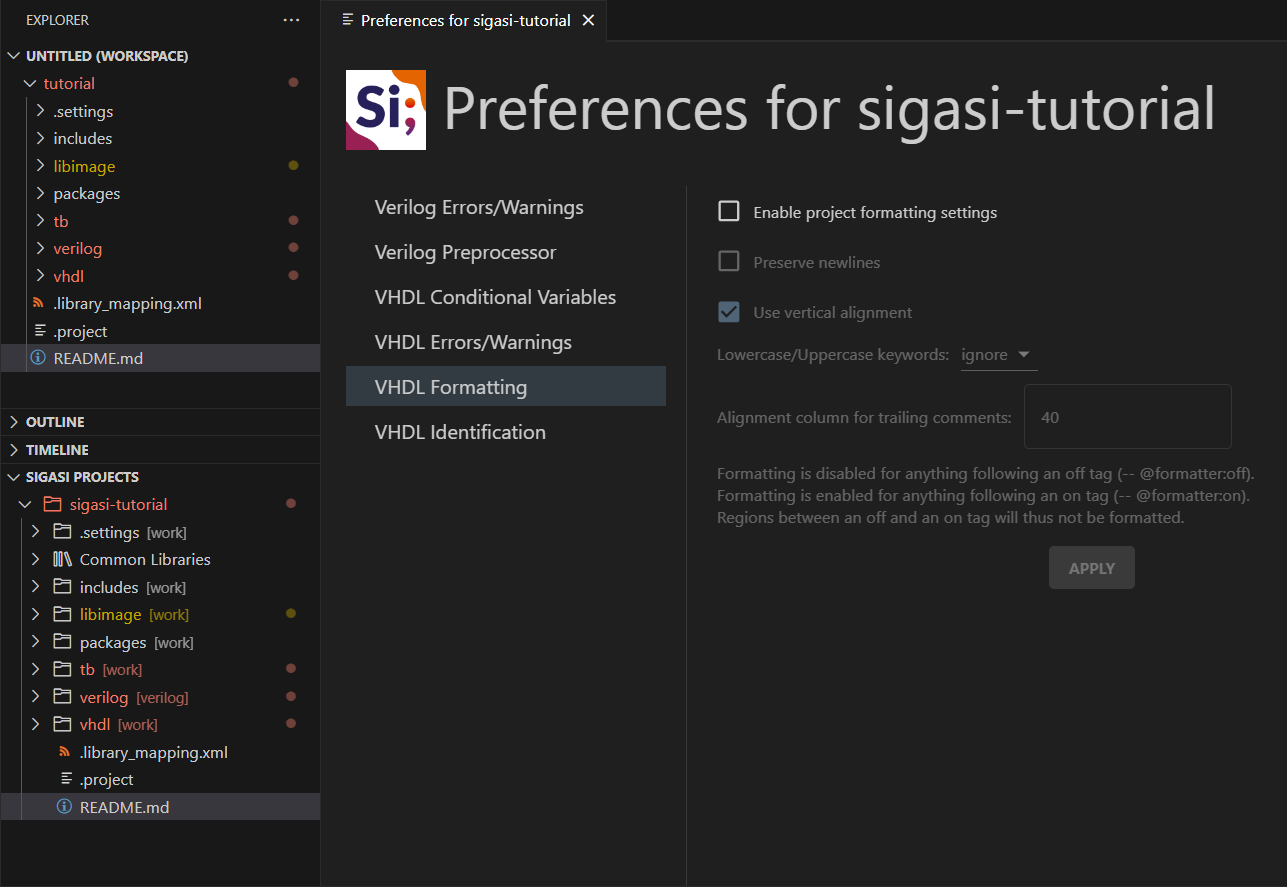
To open the Preference View, right-click the project, folder, or file you want to configure in the Sigasi Projects View. This view allows you to configure all preferences for the selected project, folder, or file.
- Change the severity of linting rules for your project
- Tweak validation parameters
- Modify conditional variables for VHDL 2019 projects
- Configure include paths and initial defines for the SystemVerilog Preprocessor
Make sure to click the APPLY button at the top right after making your changes.
Changes you make here will be stored in the .settings/ folder within your project.
This way, if you commit the settings with your project, they will be available for your fellow team members.
Configuring Linting Rules
You can configure linting rules per project, folder, or file by right-clicking a project, folder, or file > Open Preference View in the Projects View and then selecting Verilog Errors/Warnings or VHDL Errors/Warnings. In the middle of the page, Click here to enable to activate the rule configuration.
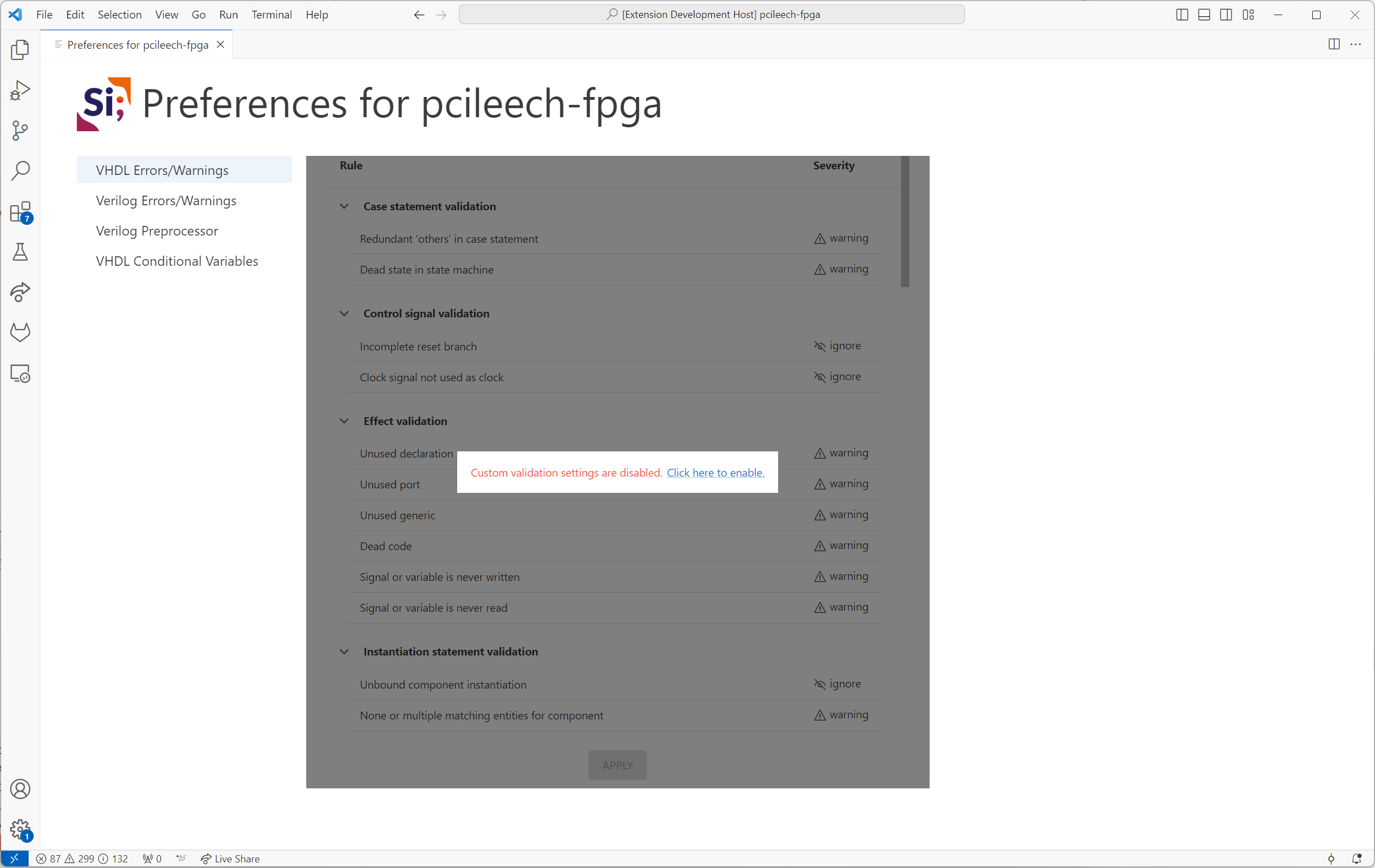
Refer to the linting documentation to learn more.
Graphical Views
Block Diagram View
Sigasi Visual HDL Professional Edition or Sigasi Visual HDL Enterprise Edition
The Block Diagram View displays a graphical view of all architectures, modules, their instantiations, and generate constructs in your selected editor’s VHDL or SystemVerilog code.
VHDL processes and SystemVerilog always blocks are also shown in the block diagram.
This view automatically updates while you are editing your code and offers a convenient way to visually inspect and navigate your code, even when it’s unfinished or broken.
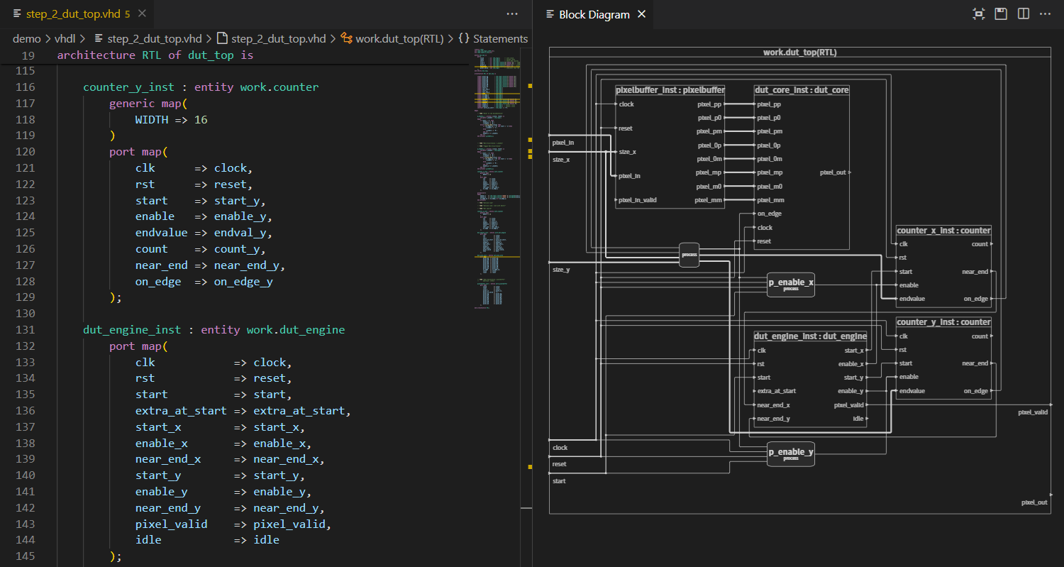
You can open the Block Diagram View by right-clicking in the editor and selecting Show In > Block Diagram. Alternatively, you can open the view using the command palette Ctrl+Shift+P and typing Sigasi: Open Block Diagram.
You can double-click blocks, ports, or wires to navigate to the corresponding HDL code. If you want to go into a block, you have to select it, right-click, and click Open Entity Declaration, Open Architecture, or Open Module.
To find an object in the Block Diagram, you can navigate from your code to the Block Diagram. In your code, right-click a signal, port, process, generate, or instantiation and select Show In > Block Diagram - just like when opening the Block Diagram View the first time. If the Block Diagram is already open, the corresponding element will be highlighted, and the Block Diagram View will center upon it.
You can export the Block Diagram View to an image with the save button on the toolbar. Both SVG and PNG are supported. Choose a *.svg filename for SVG export or a *.png filename for PNG export.
State Machines View
Sigasi Visual HDL Professional Edition or Sigasi Visual HDL Enterprise Edition
The State Machines View displays a graphical (bubble diagram) view of all state machines in your current VHDL or SystemVerilog editor. This viewer automatically updates while you are editing your code and offers a convenient way to visually inspect and navigate your code, even when your code is unfinished or broken.
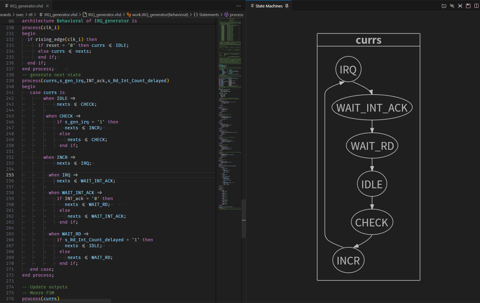
You can open the State Machine View by right-clicking in the editor and selecting Show In > State Machines. Alternatively, you can open the view using the command palette Ctrl+Shift+P and typing Sigasi: Open State Machines Diagram.
If you have documented your state transitions (i.e., the assignments), the comments will be added as text to the transitions in the view.
You can double-click nodes or transitions to navigate to the corresponding HDL code.
With the hide comments button, you can toggle the display of comments on edge labels.
With the hide conditions button, you can toggle the display of comments on edge labels. These labels show the code comments of the transition statements.
You also have the option to Zoom In, Zoom Out, or Zoom to Fit.
You can export state machines to an image with the save button. Both SVG and PNG are supported. Choose a *.svg filename for SVG export or a *.png filename for PNG export.
Dependencies View
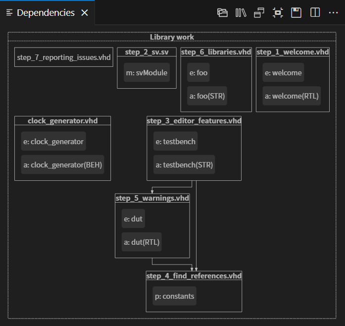
The Dependencies View visualizes the dependencies of your VHDL, SystemVerilog, or mixed language projects. This view shows the relationships between your source files and makes it easy to see top levels and important packages. The Dependencies View also makes it easy to detect orphaned files.
The view is automatically updated each time you save your files.
You can open the Dependecies View by right-clicking in the editor and selecting Show In > Dependencies.
The Dependencies View has the following options:
 shows dependencies of the entire project, which you can uncheck to focus on the active editor dependencies only
 groups design files per library
 shows design units inside design files prefixed with an abbreviation of their kind architecture, module, package, etc.
The Dependencies View can help you navigate, too. Double-click a file name in the diagram to open the corresponding editor.
You can export this diagram for documentation by clicking the save button.
UVM Diagram View
Sigasi Visual HDL Professional Edition or Sigasi Visual HDL Enterprise Edition, [Only for SystemVerilog]
The UVM Diagram View displays a graphical representation of the UVM component structure through an intuitive graphical display. It visualizes the relationships between components, their hierarchical arrangement in the topology, the connections between ports, and the referenced design interfaces. The dynamic expansion of the diagram allows for efficient tracking of connections throughout the UVM component structure.
Similar to the UVM Topology View, this diagram offers a set of navigation options for each element (both by double-clicking on elements and through the context menu), allowing you to access an element’s types, declarations, or instantiations. Double-clicking on a port connection line navigates to the corresponding connect method call in the source code.
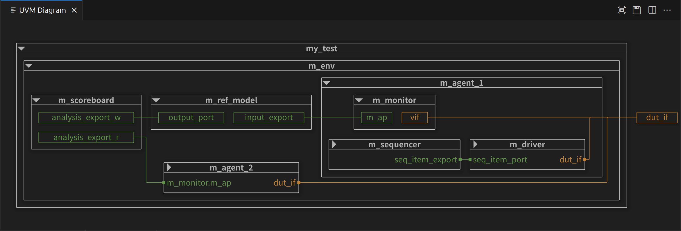
Like other diagram views, you can find buttons on the toolbar to Zoom to Fit and export the UVM Diagram as an image (supports both SVG and PNG).
Net Search View
[Only for VHDL]With Net Search, you can find a net’s loads and drivers. A net is defined as a signal or port and all other signals and ports that are directly connected to it. The loads are where you read the value of a net, and the drivers are where you write to it.
To find the entire signal or port net, place your cursor on the identifier and right-click. Then select Find Net. Alternatively, you can press Ctrl+Shift+H.
The Net Search View will appear. For big designs, it might take a while before the results appear.
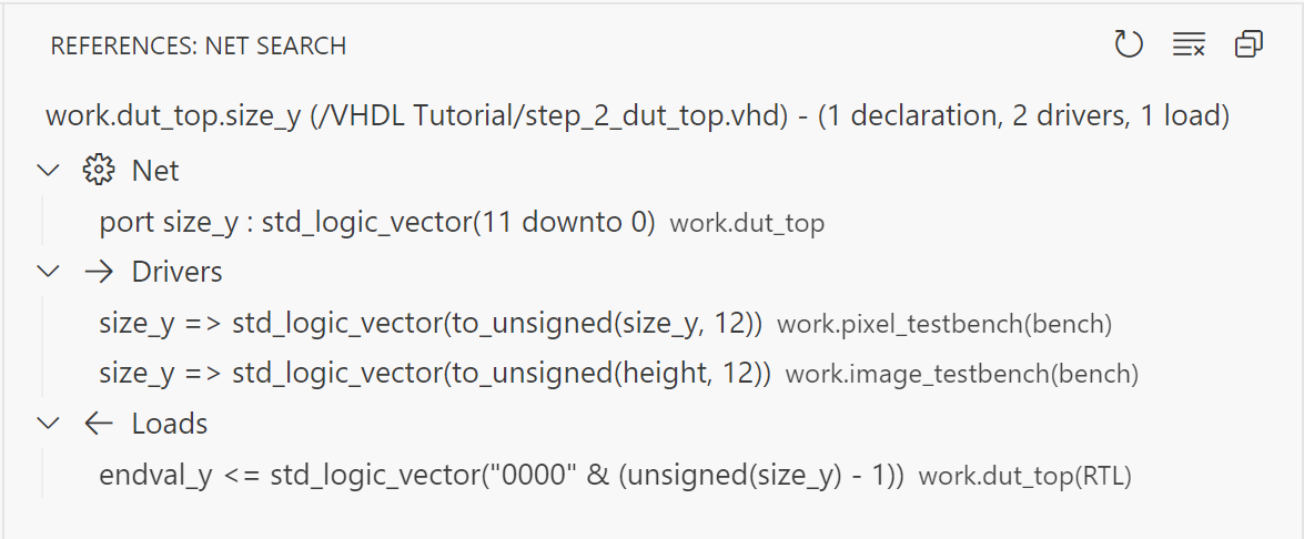
From the Net Search View, you can navigate to the code by double-clicking the search results.
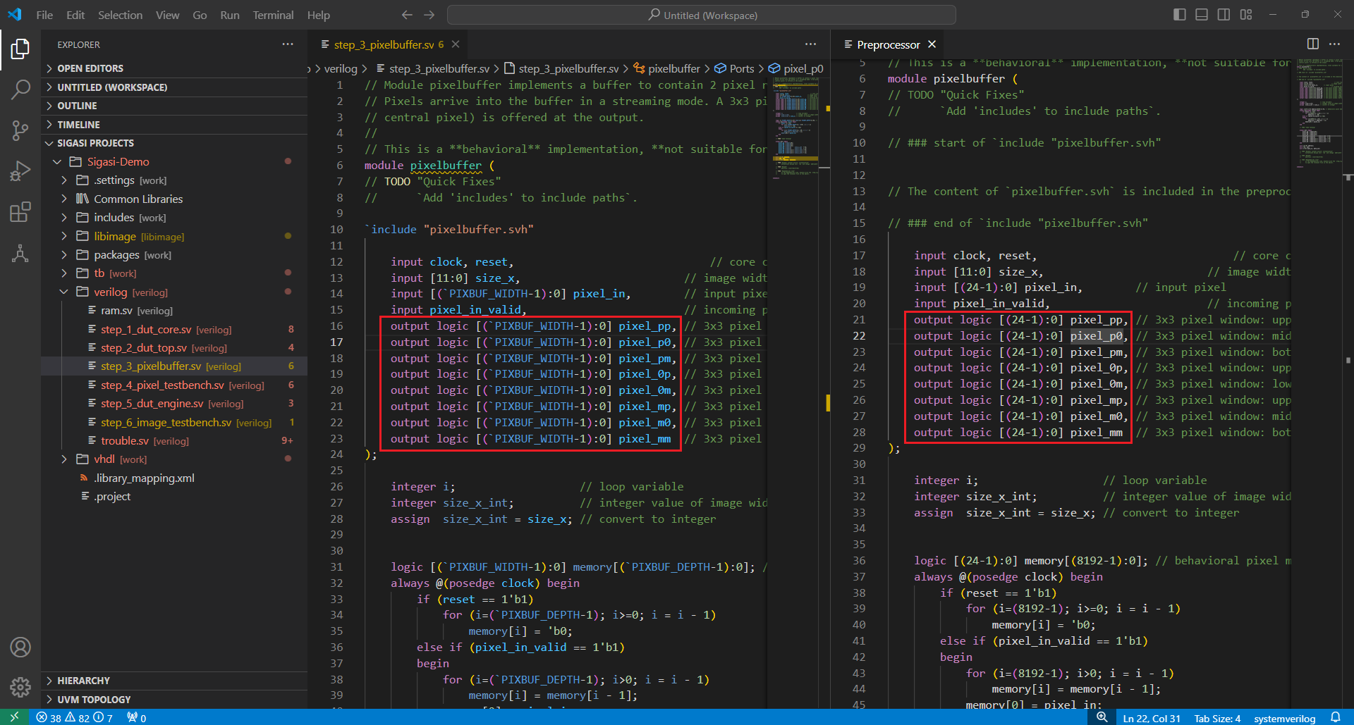
Preprocessor View
[Only for SystemVerilog]In order to open the Preprocessor View, which shows preprocessed text, right-click in the editor and select Show In > Preprocessor.
Class Hierarchy View
[Only for SystemVerilog]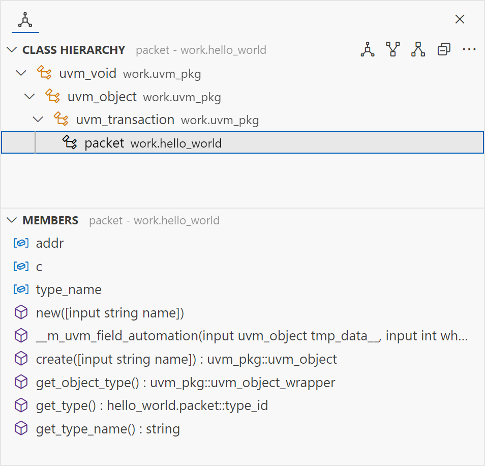
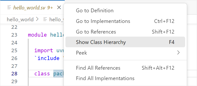
The Class Hierarchy View displays more information about the hierarchy of a class. It consists of a hierarchy tree and a list of its class members. To open the Class Hierarchy of a class, click the class name, right-click, and select Show Class Hierarchy (or press F4).
Class Hierarchy Tree
The class hierarchy tree displays the superclasses, subclasses, or both.
| Icon | Command | Description |
|---|---|---|
 | Class Hierarchy | Displays all superclasses and subclasses. |
 | Superclass Hierarchy | Displays all superclasses and implemented interface classes. |
 | Subclass Hierarchy | Displays all subclasses that extend or implement the selected (interface) class. |
| Toggle Show Qualified Class Names | Shows the qualified name next to each class. |
Member List
The member list shows all members (fields, functions, tasks, and constructors) of a selected class in the class hierarchy tree.
The icon shown in the view describes the current active state of the members list options.
| Icon | Command | Description |
|---|---|---|
 | Show Inherited Members | Shows members inherited from superclasses. |
 | Hide Inherited Members | Hides members inherited from superclasses. |
 | Show Fields | Shows fields in the members list. |
 | Hide Fields | Hides fields in the members list. |
| Toggle Sort By Defining Class | Sorts members by the class in which they are defined. |
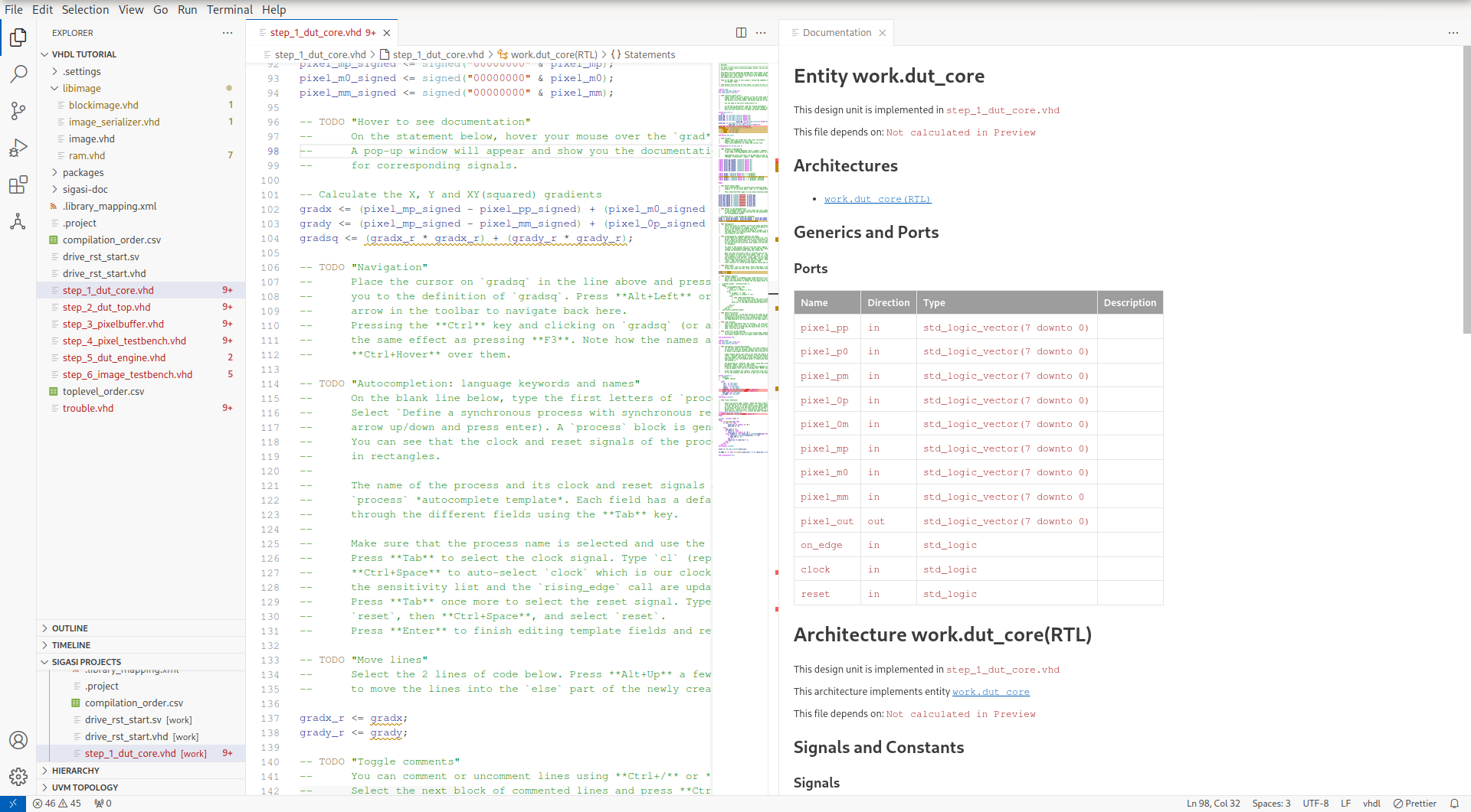
Documentation View
Sigasi Visual HDL Professional Edition or Sigasi Visual HDL Enterprise Edition
The Documentation View gives you a live preview of the automatic documentation SVH can generate for your project.